")


Camera calculator - Calculating the sensor exposure time
The calculation of the correct exposure time in case of moving parts prevents blurred images. They are produced when the pixels shift in the range of the camera while being exposed. Depending on the application, different tolerances are possible. A smear effect of 1 pixel is not visible to the eye most of the time, however, it still affects precision measurement results. Yet this value is acceptable for many standard applications. Useful exposure times for CCD cameras are between 50 µs to maximally 500 ms. Typical values in practice for "normal applications" are mainly between 0.1 and 20 ms. Using CMOS sensors, shorter exposure times of up to 1 µs can be realised, too.
If the exposure time calculation gives greater values (e.g. 50 ms), it is of course possible to use a shorter exposure time (e.g. 5 ms) if there is sufficient light. Longer exposure times are also to be avoided as vibrations can also become visible in the image.
Calculation of sensor exposure time for translational part movements (conveyor belt) using area scan cameras
Please use this calculation method for linear part movements.
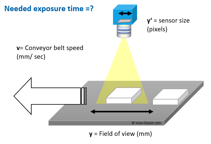
Note: Even when using the drop-down lists own values can be entered. Please use the first entry "user def."!
Further explanations and details on these calculations can be found in chapter "Exposure times for area scan cameras".
Calculating the sensor exposure time for the inspection of revolving objects using area scan cameras
The calculation of the proper exposure time is also possible with rotary movements, where cylindrical objects are inspected with an area scan camera. A possible example would be reading a data matrix code on a cylindrical component, which is rotated in front of the camera until the code has been read in by the machine vision system.
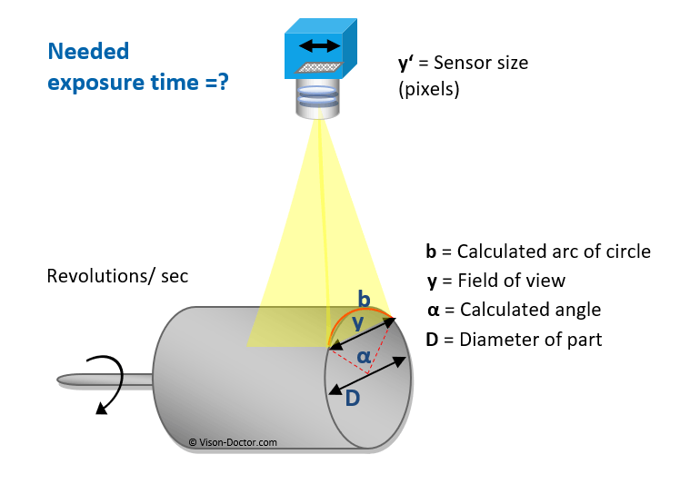
Please note that with larger angles for the arc of circle, perspective shortenings occur at the edge of the arc, which are not taken into account for the calculation. Changes in the magnification due to different working distances are also ignored.
Note: Even when using the drop-down lists own values can be entered. Please use the first entry "user def."!
Attention: Ideally, inspections of cylindrical objects are done with the help of line scan cameras. Further explanations can be found in chapter Line scan cameras.