")


Trigger functions
In most of the cases, modern imaging applications work with triggered image taking. As industrial cameras usually do not have a mechanical shutter like a single-lens reflex camera, the sensor is principally continuously exposed.
A completely free-running camera reads out the sensor permanently. Upon an "image query", the current image is first read out completely, a new image acquisition is started and then this completely captured image is transferred to the PC.
|
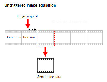
In this way, significant delays are produced which may theoretically range from zero to (almost) the maximum of the recording duration of a complete image.
In case of triggered image taking, first all electrical charges of the entire sensor are removed immediately upon the trigger signal (asynchronous reset), the image is exposed anew and then transferred to the evaluation unit.
|
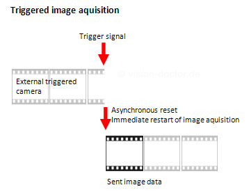
All "somewhat better" industrial cameras as well as all intelligent cameras can be operated in triggered mode and thus have a real-time response for the image acquisition. Depending on the manufacturer, however, there may be differences which nevertheless stay in the range of µs most of the time.
Hardware and software trigger and timings
In case of the hardware trigger, the triggering is induced by an external impulse which comes from a photoelectric barrier, the digital input of a PLC, initiator, etc. This impulse can be induced at the camera, in case of a frame grabber-based system, or directly at the image acquisition card. USB, FireWire and GigE vision cameras can only be triggered at the camera from the hardware side.
In case of the software trigger, the triggering is induced by the control software (machine vision programme).
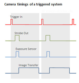
Camera timing
In case of the software trigger, the triggering is induced by the control software (machine vision programme).
|
Triggers with fixed exposure time
Normally the camera is configured in such a way that each image is exposed equally long. In former times, this was done by means of dip switches on the back of the camera or by terminal commands via serial interfaces. State-of-the-art image transfer interfaces and drivers allow for the comfortable adjustment of the exposure time directly from the camera driver / machine vision software.
Pulse width control
For fast changes to exposure times from image to image, a PWC mode has been introduced particularly for analogue cameras, as the response for changing the exposure times via serial interfaces was too slow. Via an additional signal line, the duration of the exposure can be defined for each image.
Multi-triggers and frame buffers
Some industrial cameras have special multi-trigger functions integrated.
One single trigger pulse internally sets off several fast image acquisitions. These images are often captured using different pre-configured exposure parameters. In this way, an object can be captured using different image brightness. This may, for example, be important in traffic applications (number plate / driver / vehicle recognition). The images are stored in internal frame buffers and then transferred.
Post-triggers and frame buffers
This special trigger mode also requires a camera with an additional frame buffer.
In this case, the camera continuously captures images (free-running or triggered mode) and stores them in internal frame buffers. A total of 20 images, for instance, can be buffered in the camera in this way. The camera can be configured upon a trigger / error signal in such way that further images are taken and a sequence is transmitted then, which, for instance, represents 10 images before the trigger event and 10 images after the event. Using this technology you can, for example, examine how a system error occurred, before the actual malfunction message is generated.