")


Inspecting with backlight illumination
Transmitted light illumination is the first choice of lighting when it is necessary to measure parts as accurately as possible. The lighting is arranged on the opposite side of the camera, the component itself is put in the light beam.
For this purpose, the inspected part can...
- be on a preferably transparent conveyor, but also very bright conveyors can be screened using red or infrared light.
- be situated on a glass plate. It should be made of tempered glass, so that as few scratches develop on the surface as possible.
- be transported in a guide rail. This is interrupted where the part is supposed to be measured.
- be held by a robot or gripper system above the light.
The component itself is only recognisable as a silhouette, no statement can be made about the surface of the part. The area surrounding the object is the illumination into which the camera system looks. Because of this massively excessive light, the entire application is relatively resistant to stray light.
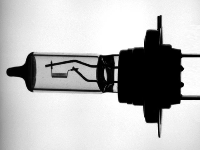
Backlight image incandescent lamp
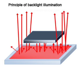
Working principle backlight
Important for machine vision
In order to achieve the best measuring results, background illumination is used which...
- is as homogeneous as possible over the entire light emitting surface. In this way it is possible to use measurements from the centre towards the margin.
- emits preferably parallel light, avoiding shade effects at the edges. The higher the contrast difference at the edge, the more accurate the results returned by the image processing software.
- never over-exposes the image in measuring applications. When using CCD sensors, there will be a blooming effect if the pixels are saturated by over 100 per cent. Excessive electric charges migrate into neighbouring pixels which will also be overexposed in this way. The consequence are "thinner" silhouettes, the user gets completely wrong results. A CMOS sensor does not show this effect, since each pixel is read out individually; however, it is not quite suitable for precision measurements as it has a rather logarithmic sensitivity to light and makes it difficult to interpolate measured values.
Contrast enhancement by avoiding stray light or collimation
All methods to prevent stray light create sharper edges richer in contrast in transmitted light as partial shade effects as edge fringes disappear in this way:
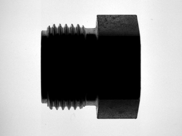
Backlight - close to object
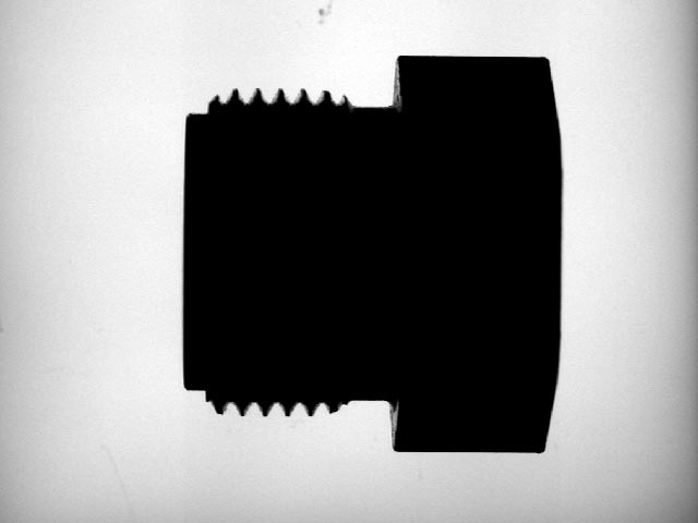
Backlight - far away
- Increased distance from the background illumination to the test object: if the object is, for example, 10 cm away from the light instead of 1 cm, half-shade zones are prevented. The diffuse scattered light is simply less intense than light directly oriented towards the camera and is no longer relevant in case of a large working distance.
- Masking the background illumination: if a diffuse background illumination must nevertheless be mounted very close, half-shade zones can be prevented by masking (covering) the areas which are not required.
- Using a light control film: a filter plate on the illumination blocks diffuse stray light and passes only vertically emitted light. Half-shade zones are prevented in this way.
- Using a telecentric background illumination: the backlight is aligned absolutely in parallel by means of an optic lens system. Half-shade zones are prevented in this way. This method should always be applied in combination with telecentric lenses and leads to perfect results.
Contrast enhancement by means of polarisation
By using a polarizing filter on backlight and optics, the test object can be partially darkened by means of the effect of photoelasticity in case of transparent, hard plastics. Particularly highly transparent materials hardly generate any contrast in transmitted light, which is required to find the object or edges. This technique serves to increase the contrast and enhance an evaluation.
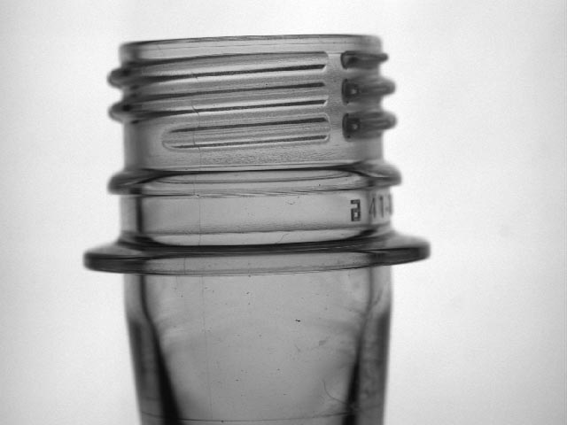
Regular backlight
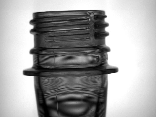
Polarized backlight
Contrast enhancement using short-wave light
Particularly transparent and semi-transparent objects are screened in transmitted light, there is hardly any contrast and the objects are difficult to evaluate. Due to the smaller wavelength, short-wave light strays to a greater extent than longer-wave light. In this case, the use of blue instead of red light produced more than 10 per cent additional contrast.
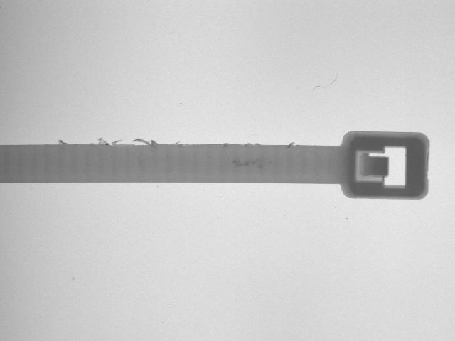
Red LED backlight
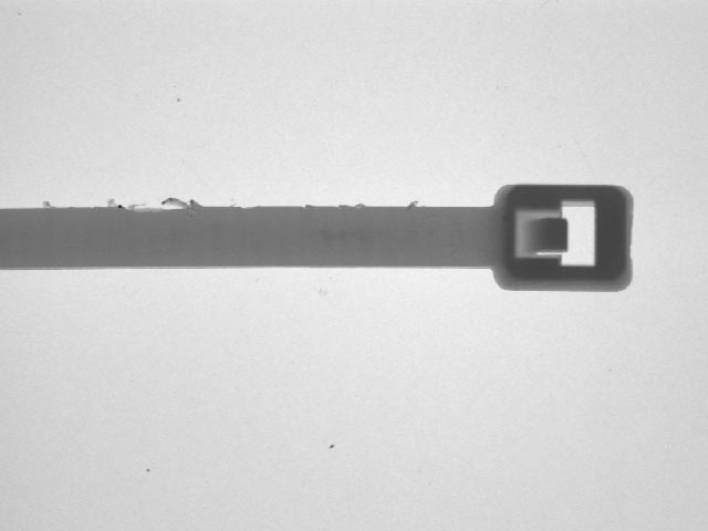
Blue LED backlight