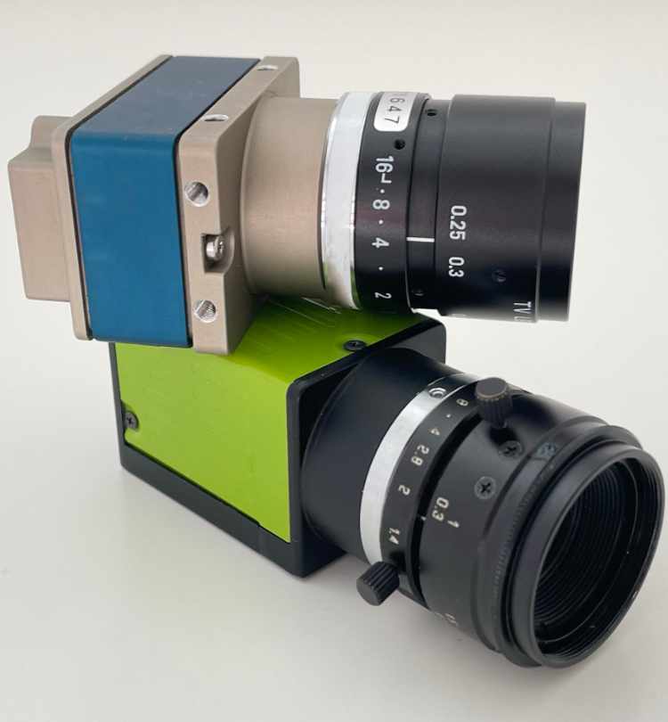


The main aim of calibration is to produce an absolutely homogeneous grey image. Deviations from an ideal image can occur for a number of reasons:
These variations can lead to typical image defects such as
These distortions make it difficult to evaluate the image using image processing software. In addition, mechanical misalignment and optical distortion can also distort the image.
A calibration chart helps to identify and correct these errors and deviations. It performs several functions at the same time and ensures that image quality and evaluation accuracy are improved.
More details on (re)calibration:
Before starting to develop a software application, the initial image must be as PERFECT as possible.
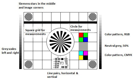
A suitable encoder configuration and appropriate multiplier/divider settings on the camera's line trigger input must first be used to produce a distortion-free image.
Do not rely on your eye, but measure the shape of circles or squares in the X and Y directions, for example using a calibration grid. This is the only way to be sure that you are capturing distortion-free images of good quality.

In any case, the first step should be to ensure that the lighting accurately covers the image area to be captured. Tips on lighting alignment can be found here.
Once the image composition in the X and Y directions and the image brightness are approximately correct, the next step is fine tuning. In our image above, you can still see large variations in brightness in the X direction.
To compensate for these inhomogeneities, every major line scan camera manufacturer supplies a ready-made software interface for calibrating the camera.
Calibration is done in two or three steps:
(The calibration steps are called PRNU, FPU, DNU: Dark Signal Non Uniformity, Fixed Pattern Noise, Photo Response Non Uniformity).

Any vertical streaks in the image should have disappeared and the image should appear smooth. Make any final fine adjustments to the camera's exposure time, gain and lens aperture and refocus the lens.
Any vertical streaks in the image should have disappeared and the image should appear smooth. Make any final fine adjustments to the camera's exposure time, gain and lens aperture, and refocus the lens.
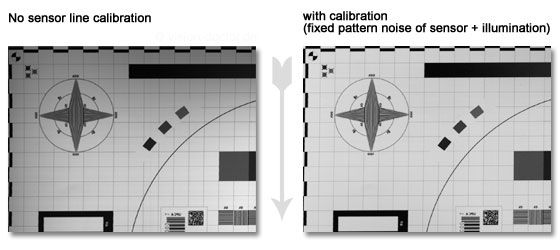
Horizontal streaks are also rare. These can have several causes:
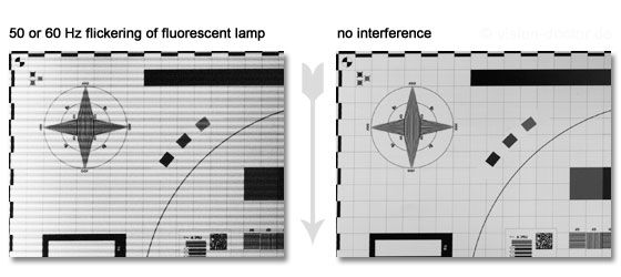
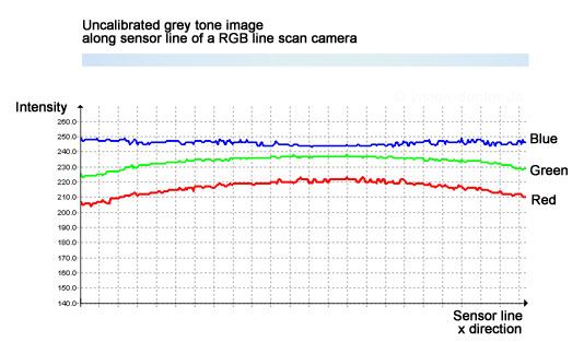
Any colour camera, including line scan cameras, needs to be white balanced to achieve neutral colours. Due to the colour temperature of the white light used (spectra of different white LEDs), the distribution of red, green and blue intensities in the camera image is inhomogeneous. The different spectral sensitivity of the sensor to different wavelengths further exacerbates this effect.
The image and distance intensity diagram of a colour line scan camera shown here shows two typical errors that need to be calibrated:
Vision-Doctor.com is a private, independent, non-commercial homepage project and not a technology provider or system integrator. Suitable technologies and further professional support can be obtained from the companies & partners listed below.
If necessary, I will be happy to provide a quick recommendation, contacts and brief information.
