")


Perfect alignment of the camera system
Initial situation
Often the camera is simply screwed on, the image detail is adjusted via the monitor by slightly moving and tilting the camera and then the software programming of the camera starts. For not very challenging tasks, such as part presence checks, this can be sufficient.
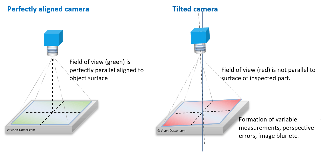
But this approach almost guarantees that the vision system does not look perfectly perpendicularly onto the object, which will, for example, lead to:
- inaccuracies in the measurement caused by a variable imaging scale, as the working distances in the centre of the image and the image margins vary.
- problems in tracking the tools as coordinate systems, too, do not provide uniform results, unless a precise part feed (e.g. rotary table) is used.
|
It can equally be assumed that the camera system was not exactly focused, which can lead to further blurring and loss in contrast, especially in the peripheral areas of the images. This will additionally impair the optical detection abilities of the machine vision system.
Tips for proper adjustment of the camera in incident light
By which simple means can we determine whether a camera was mounted exactly vertically? The camera mount may indeed be right over the inspected part, but smallest mechanical tilting of the mounting plate may cause greater deviations due to the large working distances.
The "mirror trick":
A mirror simplifies the alignment significantly. It is simply placed in the centre of the image field of the camera. Via the monitor the reflection can now be viewed in the camera image.
|
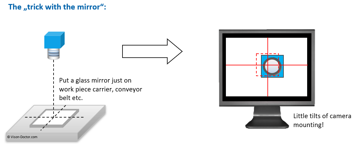
In case of a precisely vertical arrangement, the reflection is exactly in the centre, if the camera is slightly tilted, the object is shifted out of the middle of the video image. A self-generated hair cross or reference point precisely in the centre of the image display window helps for the exact alignment: in case of a resolution of 1600 x 1200 pixels, the centre of the marking will be at x = 800, y = 600.
This trick can be applied to incident light and transmitted light applications. It may be necessary for these purposes to change focus and aperture of the lens so that you can clearly see the reflection. Therefore adjust the optics correctly only afterwards. The correct focusing of the lens is individually described in the document "Precise lens focusing”.
Use of appropriate brackets for mounting
With the help of XY-slides, turntables, pan/tilt units or ball heads, a much finer adjustment can be made than when using a simple camera mount with one, two slots and slide blocks in the Bosch profile. Please include a proper, stable mount when planning the camera mounting!
Tipp:
Further instructions, calibration charts, Siemens star, etc. can be found in the "Service" menu of this website for download.