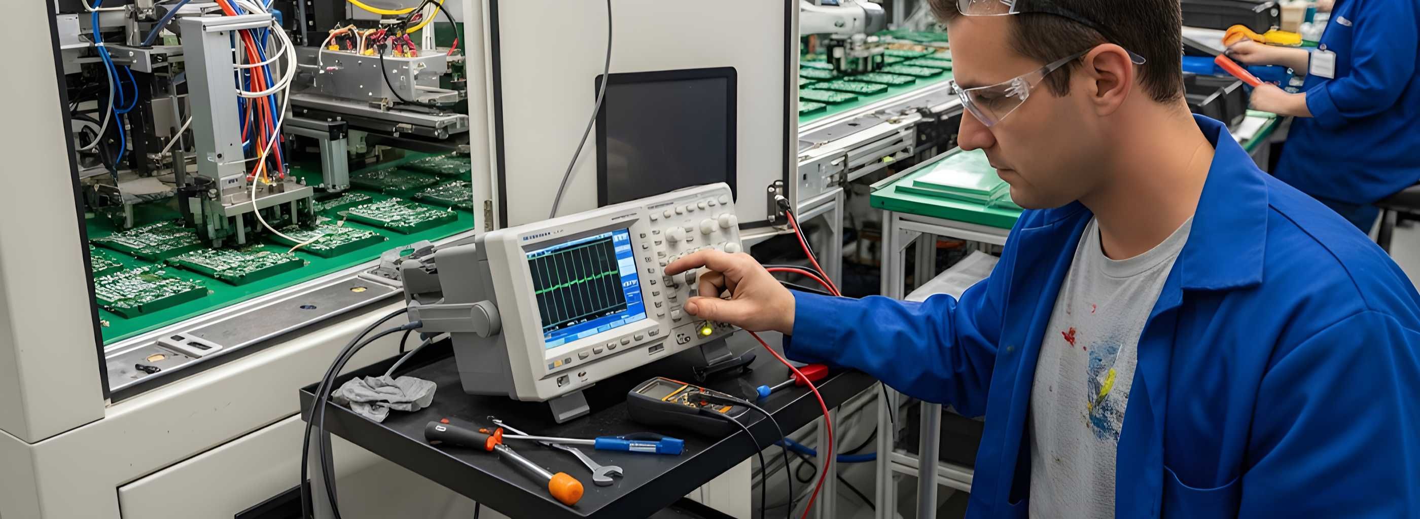
Troubleshooting
Detecting and fixing errors &
system malfunctions in machine vision systems
Initial situation: High system complexity
Machine vision systems have become indispensable in industrial automation, but their complexity can make troubleshooting challenging. A systematic approach is essential for identifying and resolving malfunctions.
A typical 2D machine vision system consists of several components that work together, including lighting, a lens with a filter, a camera with a sensor, a bus system, an interface and image processing software. Problems can arise in any of these areas.
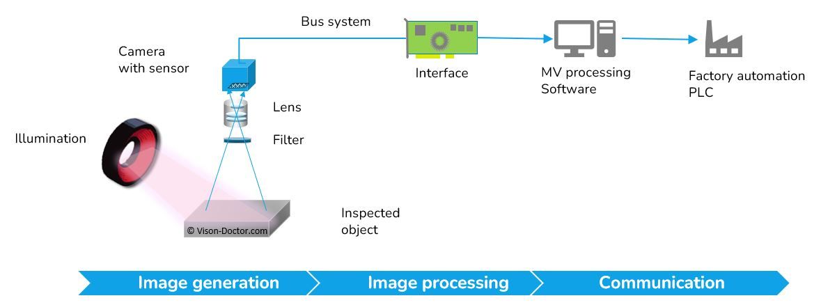
Where is the bug?
If an industrial camera inspection system suddenly malfunctions or produces incorrect results, it is essential to troubleshoot the issue rapidly and systematically. Causes can range from simple environmental influences and mechanical changes to more complex software and hardware problems.
To minimise downtime, it is important to check the most common sources of error specifically, such as lighting, optics, cable breaks, and communication and driver problems. Taking a structured approach helps to quickly identify the actual cause and restore the system to full functionality.
Systematic and structured troubleshooting
1. Stay calm
The first step is to take your time and develop a clear testing strategy.
2. Testing, simplifying, and excluding
Reduce system complexity by testing components individually and checking their basic functions. For instance, test the system in free-running mode, independently of PLC control.
3. Further self-help
Are there any system logs on your test system that could be helpful?
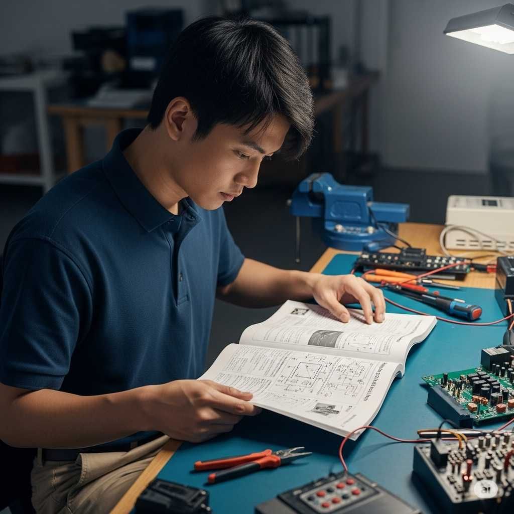
Before requesting external support, please consult the user manual and the manufacturer's knowledge base. Talk to experienced colleagues.
4. Contact support
If you cannot identify the cause of the issue, contact the official manufacturer or supplier support team. Have all the relevant information ready, including details of the hardware and software versions, a description of the error and the steps you have already taken.
Common hardware and software errors
Malfunctions can occur for a variety of reasons. Taking a structured approach can help you quickly identify the cause.
Check the following:
-
Hardware defects
-
Cable break
-
communication errors
-
Software parameterization
-
Trigger and encoder
-
Software changes
-
Drivers and firmware
-
Mechanical changes
-
Environmental influences
-
Optics
-
Illumination
-
Camera device
-
PC & Interface cards
-
External control (PLC, network, etc.)
Human error
Problems can be caused by stress, overload, inattention, misinterpretations, a lack of knowledge or communication errors. To avoid these in future, it is recommended that training and checklists are implemented, and that a dual control principle and better working atmosphere are established.
A full working day can easily lead to mistakes:
- Inattentiveness
- Stress and overload
- Misinterpretation
- Routine blindness
- Self-Assessment
- Communication errors
- Gaps in knowledge
- Fatigue

General, system-related influences
Tilted objects
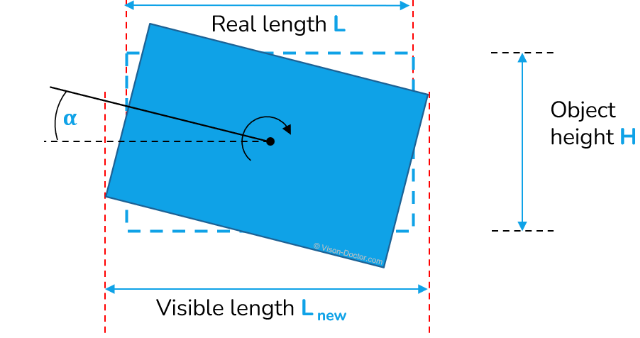
Even a slight tilt of the test object can cause deviations in length measurements. Even a telecentric lens can not really minimise this problem, precise positioning of the object remains essential.
Motion blur
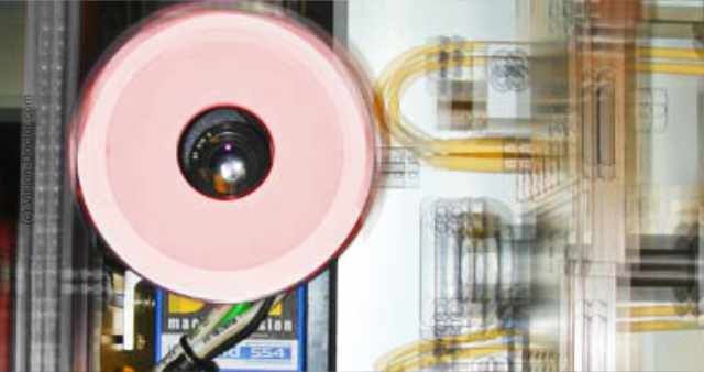
This occurs when the object moves while the sensor is exposed. This results in blurred images. Possible solutions include reducing the exposure time, using stronger lighting, increasing the aperture size, or raising the camera gain.
Positioning effects
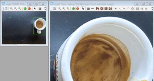
Perspective distortions can be caused by deviations in the X and Y position of the object. This can be remedied by improving mechanical positioning or using telecentric lenses.
Environmental influences
The environment has a significant impact on the performance of an image processing system.
Vibrations
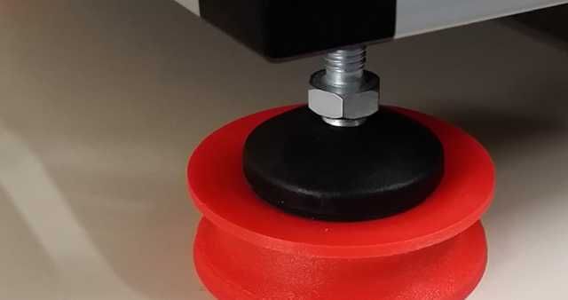
Machine vibrations can cause images to appear blurred. The effects can be reduced using vibration dampers and hardware decoupling.
Dust, dirt, and moisture
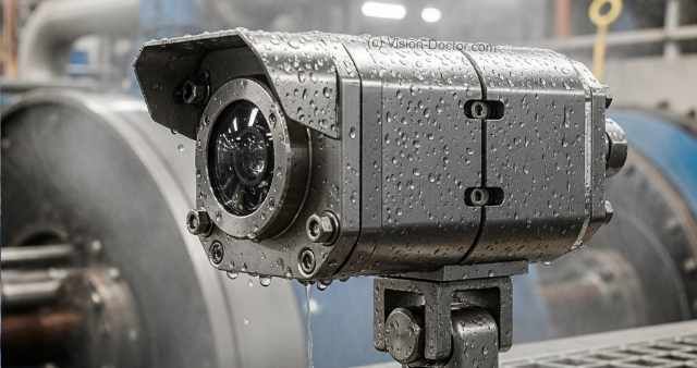
Dirt particles can contaminate lenses and damage electronic components. Using IP-certified housings or air curtains protects the components.
Extraneous light
Disturbing light sources from outside (e.g., windows or ceiling lights) can overexpose the image or reduce contrast. Enclosing the system or using bandpass filters in combination with monochromatic LEDs eliminates this problem.
Heat

High temperatures can increase sensor noise and shorten the service life of electronics. Cooling housings and heat reflection filters are effective solutions to this problem.
Electromagnetic radiation
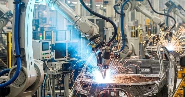
EMC interference can result in incorrect trigger signals or damaged data. Important protective measures include improved shielding, correct grounding and the alternative use of fibre optic cables.
Practical examples of common mistakes
Systematic troubleshooting is crucial when faults occur in an industrial camera inspection system, as it enables production to be quickly restored. As the causes can be very diverse, it is important to consider all possible sources of error. The following are some typical scenarios and their possible causes:
“Image acquisition failed”
One of the most common and confusing problems in industrial image processing is a completely black image. This indicates that either no light is reaching the camera, or the signal is being lost en route to the PC. Systematic troubleshooting requires a thorough examination of both the hardware and the software.
- Basic Optical and Lighting Check
Is the lighting on/off?
First, check whether the lighting is active at all. See if the light is on, or test it separately as described in the previous example to rule out a defect.
Is the lens aperture misaligned?
A common but simple cause that is often overlooked is an accidentally closed or misaligned aperture (iris). Visually inspect the lens and make sure the aperture is fully open.
- Hardware and Cable Check
Hardware defects:
Both the camera and the lighting can be defective. If the lighting is working and the aperture is open, the camera itself may be faulty.
Broken cable:
Check all cable connections. A broken cable in the camera's power supply, the trigger cable, or the image transfer cable (e.g., Ethernet or USB) can lead to a complete failure of image capture.
- Software and Trigger Check
Software / Hardware Trigger Configuration:
Make sure the trigger settings in the software are correct. An incorrectly configured trigger can cause the camera not to fire at the right time or to completely refuse to capture an image.
Is there a PLC Trigger In > Strobe Out signal?
Check the interaction between the PLC, camera, and strobe controller. Is the PLC even sending a trigger signal? And is this converted by the software into a 'Strobe Out' signal for the lighting?
Freerunning test:
Switch the camera to freerunning mode (without a PLC trigger). If an image is captured in this mode, the problem lies with the trigger communication.
- Advanced Diagnosis
Testing with an oscilloscope:
An oscilloscope can be used to accurately check the trigger signal. Measure whether the PLC's trigger signal is correctly arriving at the camera's input and whether the camera is sending the corresponding 'Strobe Out' signal.
Testing with new software program without tools:
Sometimes, a fault can lie in a complex software program or a specific tool. Test the camera with a simple, standard image capture program from the manufacturer to see if image capture works fundamentally. If so, the problem lies in the complexity or configuration of the main application software.
The light source is not working
When the lighting in an industrial camera system fails, it's often the most obvious cause of faulty images. The troubleshooting process should include both hardware and software checks.
- Hardware Check
Is the light defective? The simplest and first check is to test the lighting independently of the camera system. Connect the light directly to a suitable power source to see if it still illuminates at all. If the light itself isn't working, it's defective and needs to be replaced.
Hardware defect / Broken cable: Check all cable connections between the controller (PLC), the strobe controller, and the lighting. A loose connector or a damaged cable can interrupt the signal transmission. Check the strobe controller: does it show status lights or error messages?
Strobe controller configuration: Many strobe controllers have their own settings or a user interface. Check that the controller is configured correctly, especially regarding current and pulse duration.
- Software Check
PLC trigger: Ensure that the PLC is actually sending a trigger signal. Check the status of the "Trigger In" signal at the camera or the strobe controller.
Strobe Out signal software: Check whether the software sends the "Strobe Out" signal to the strobe controller when a trigger is received. This can be done by monitoring the signal in the software or by testing in a "freerunning" mode without a PLC connection.
Freerunning test: The best method for separating software and trigger issues from hardware is the "freerunning test." Configure the camera and strobe controller so that the light illuminates in a continuous mode or an internally triggered mode without requiring an external signal (e.g., from the PLC). If the light works in this mode, the problem lies in the control by the PLC or the communication between the devices.
By systematically working through these steps, the source of the fault can be quickly located and resolved to avoid unnecessary production downtime.
Error management as a professional strategy
The effectiveness of an industrial camera inspection system depends on its availability. Errors can lead to production downtime, quality losses and high costs.
Effective error management is therefore essential to ensure and continuously optimise system performance. This involves much more than just troubleshooting; it is a strategic approach that considers the entire value chain.
In addition to technological factors, a culture of openness about errors is essential. This involves carefully documenting all errors and facilitating constant feedback and communication. By doing so, lessons can be learned from every malfunction to help improve systems continuously.
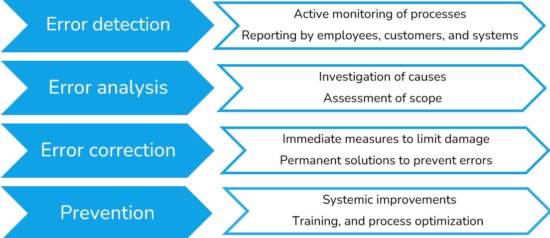
1. Error detection
The key to successful troubleshooting is the early detection of deviations. This can be achieved by actively monitoring the entire testing process. Employees, customers and the systems themselves are also important sources of information. Combining technical monitoring with human feedback enables potential problems to be identified before they develop into serious malfunctions.
2. Error analysis
As soon as an error is reported, the critical phase of error analysis begins. At this stage, the cause is investigated. It is determined not only what went wrong, but also why. The scope of the error is assessed, ranging from minor deviations to potential production stoppages. This detailed investigation of the cause is crucial in order to take the right measures.
3. Troubleshooting
Once the cause has been identified, steps are taken immediately to rectify the error. There are two types of measure:
- Immediate measures: Rapid action is required now. These measures are implemented immediately to limit damage and ensure that production can resume as quickly as possible.
- Permanent solutions: At the same time, sustainable solutions are developed to prevent the same error from recurring. The goal is to improve system stability and efficiency in the long term.
4. Prevention
The final and most important step is prevention. Findings from error analyses are used to remedy systemic weaknesses. This includes:
- Systemic improvements: - Adjustments to software and hardware to eliminate future sources of error from the outset.
- Training: Employees are trained to improve their understanding of the systems and enable them to operate optimally.
- Process optimisations: Workflows surrounding the testing system are reviewed and optimised to ensure smooth integration.
5. Documentation & Feedback
Further concluding steps:
- Documentation: Every error, its analysis and the measures taken are carefully documented. This knowledge base serves as a valuable resource for future optimisations and training.
- Feedback and communication: Constant exchange of information between all parties involved is encouraged. Open feedback and clear communication enable us to learn from every disruption and continuously improve our services.
Need help selecting a system?
Vision-Doctor.com is a private, independent, non-commercial homepage project and not a technology provider or system integrator. Suitable technologies and further professional support can be obtained from the companies & partners listed below.
If necessary, I will be happy to provide a quick recommendation, contacts and brief information.


