")


Interference filters
These filter glasses also have a large number of designations named after the principle of operation: daylight-permeable filters, UV elimination filters, UV and IR elimination filters or band-pass filters all fall within this category. Their principle of operation is based on the translucence for particular wavelength ranges and the elimination of other frequencies due to interference.
 |
For this purpose, several metallic reflection layers and thin dielectric achromatic layers are evaporated onto clear glass. On each boundary between two materials of a different refractive index, the incident electromagnetic radiation can pass and is split into a reflecting portion. A great number of partial rays are formed at the many boundaries, which interfere and can eliminate each other.
Physical principals of interference filters
The occurrence of interference effects is typical for the wave-characteristic of electromagnetic radiation, i.e. our light. Coherently oscillating waves of the same length and polarisation, which interfere, accumulate or compensate each other depending on the phasing and amplitude of the electric field strength.
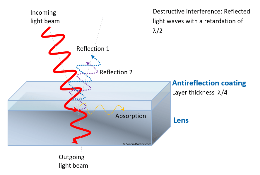
Interference filters use the phenomenon of interference in order to preferably transmit or reflect particular spectral ranges of the electromagnetic radiation. In order to achieve this effect, a great number of thin coatings with different refractive indices is applied to neutral glass. The optical thickness of these layers is usually a quarter of a defined central wavelength or multiples of it ("lambda/4 coatings"). When the electromagnetic radiation hits these coatings, it is split into a passing, a reflected and an absorbed portion on each boundary between two materials of different refractive indices. The same split-up occurs on any further boundary so that a great number of partial rays is generated which overlap and interfere constructively or destructively.
 |
As this effect strongly depends on the wavelength, many coatings with different thicknesses must be combined in order to cover a larger wavelength range.
Depending on the evaporated metal used, a great deal of spectral characteristics regarding high transmission or high reflection can be achieved.
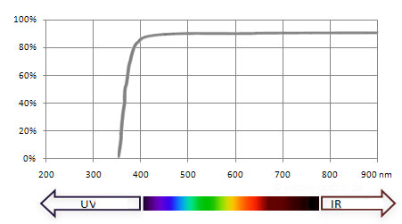
UV elimination filters (UV cut)
block the wavelengths of the spectrum below approximately 400 nm.
 |
High UV portions can sometimes be generated in daylight in case of outdoor applications or when using mercury vapour lamps and fluorescent lamps. Even when using UV light directly in the application, it should often be blocked in order to observe the fluorescence of glue, for instance, which usually absorbs light in the UV range but reflects light in the visible range. Blocking the UV portion generates high-contrast images, as the chromatic longitudinal error (chromatic aberration) and chromatic lateral error are avoided. Any blue cast is also avoided.
The UV elimination filter appears almost completely translucent from the outside, i.e. when used with a colour camera there is no colour-changing effect.
Daylight-permeable filters (UV and IR cut)
This filter type is often used with colour cameras. This filter passes the range from 400 - 700 nm of the visible light, but blocks the wavelength ranges of ultraviolet and infrared light.
 |
For this purpose, several interference coatings are evaporated onto both sides of absolutely clear filter glass. Like the UV elimination filter, it avoids chromatic aberration which leads to blurred images poor in contrast. In addition to the UV range, also the IR range of light is blocked which would also result in colour-changed images, as CCD sensors are very sensitive to IR light which would be interpreted as red. In case of colour cameras, this filter is very often integrated in the camera housing before the sensor. The same effect of overemphasis of blue and, in particular, red image information can be observed when using a monochrome camera and the corresponding light, too, so that this filter is also used there.
Suitable for colour and monochrome cameras.
Narrow-banded band-pass filters
This filter type is very often used for laser applications. The half width can be almost any width (+/- 10, 25, 50 nm) and in an extreme case only +/- 2 or 5 nm for a defined wavelength. The narrower the band-pass range, the lower the transmission of the filter. These filters are suitable for colour and monochrome cameras. There are suitable band-pass filters with different half widths for almost every wavelength.
 |
Typical technical applications:
- protection of the camera against intensive laser beams (e.g. labelling laser)
- observation of laser light of a particular wavelength in triangulation processes
- technical inspection of the fluorescent light of glue based on the excitation by UV radiation
- evaluation of faintly glowing luminescence or fluorescence effects in biochemistry and genetics
Important for imaging
When the glass warms up, the central wavelength of interference filters shifts linearly towards longer wavelengths; when the angle of incidence of the ray of light on the glass surface increases, the central wavelength shifts towards shorter wavelengths. Particularly in case of very narrow-banded band-pass filters in combination with very wide-angled lenses, this may lead to negative effects: There may be shading at the picture margin, as the filter effect can be shifted in such a way due to extremely small angles of incidence that the narrow-banded band-pass filter blocks the wavelength ranges which it is supposed to let pass.
Technical specifications of (band-pass) filters
- The transmission (T) defines the translucence of the filter in case of a particular wavelength or an entire spectrum.
- Most of the time, the peak or central wavelength (CWL) is indicated at which the maximum transmission is reached.
- The average wavelength (AWL) defines the wavelength of the light at which 50 per cent of the maximum transmission is reached.