Camera electronics
Excellent camera electronics for correct signal processing are the measure of all things. The correct processing and digitalising of the sensor data can be quite different despite a 100% identical sensor, depending on the manufacturer. Only here it becomes apparent how good a camera manufacturer and the camera electronics really are. Finally, the hardware should remain as cool as possible, as the signal noise is mainly caused by heat. Unfortunately the data sheets of camera manufacturers only provide little and hardly standardised information so that the general user cannot make a cross-manufacturer comparison. The EMVA standard 1288 is supposed to solve this problem.
Important terms regarding camera electronics are explained below:
Dynamic range of a camera signal
The specification of the signal levels of the camera sensor is usually made in decibels (dB). By means of this logarithmic ratio, very large numeric values can be illustrated in a simple way. A doubling of the performance corresponds to approximately 3 dB, this corresponds to the gain of one additional data bit. The tenfold increase of the signal corresponds to a change by 10 dB according to the logarithmic scale.
The theoretical dynamic range of the digitalisation rates of CCDs is between approximately 50 and 80 dB.
An image with n bits of signal information contains:
- 8 bits > 256 grey levels > 48 dB
- 10 bits > 1024 grey levels > 60 dB
- 12 bits > 4096 grey levels > 72 dB
- 14 bits > 16386 grey levels > 84 dB
The specification of the bit depth of the transmitted camera data and the specification of the internal processing accuracy in x bits are far from corresponding image information in shades of grey. However, the specification of the internal bit depth of the digitalisation allows for the conclusion of a possible accuracy. The data are mostly put out at 8 bits, on request also at 10 or 12 bits.
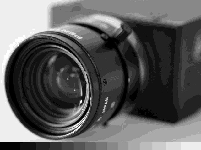
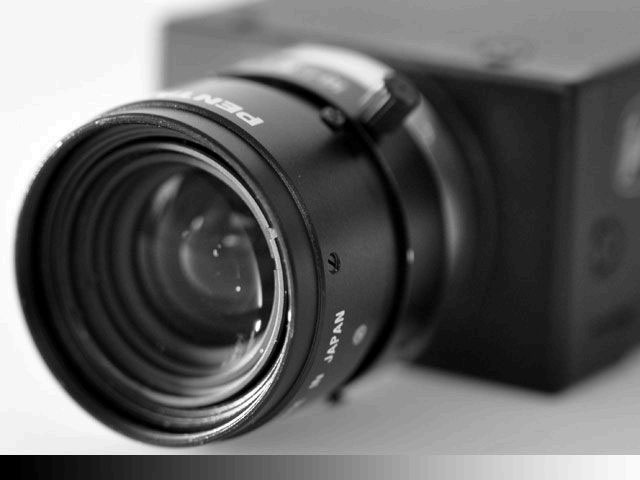
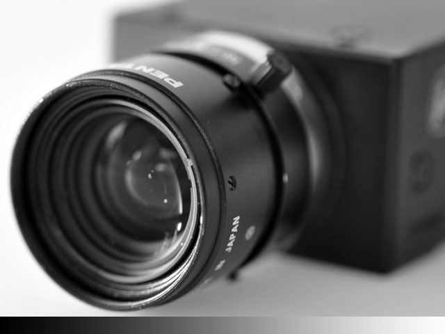
Example: images with 4, 6 and 8 bits of signal information
Gray image 4Bit
Gray image 6Bit
Gray image 8Bit
The higher the dynamic range, the more shades of grey can finally be differentiated by the camera system. Eventually, this means a better contrast and perfect grey shade gradients in the image.
Noise and signal-to-noise ratio
The noise of a camera is generated by a large number of factors. Noise is created by the thermal agitation of electrons in electric conductors. It becomes apparent in the resulting camera image in the form of a random grey pattern varying from image to image. In practice, the shades of grey vary by several per cent despite a homogeneous illumination on a homogeneous surface. Sensor noise, digitalisation noise and the noise of all electronic components add up to an overall error which impairs the video image.
An important quantity to indicate the signal quality is the signal-noise ratio S/N (signal-to-noise). The worse the value, the more the measured values vary. Just like the signal information, this value can be indicated in dB. For this purpose, the signal power S is determined and then the noise power N with switched-off signal.
SN = 10 * lg (S / R) dB
The signal/noise ratio of modern industrial CCD cameras is approximately 56 dB.
Dark current and hot pixels
When the camera sensor is covered and no light incides, it becomes apparent that weak signals nevertheless appear. This is called dark current and is caused by the formation of spontaneous free charge carriers on the light-sensitive sensor. Like light photons, ambient heat as energy supply can be sufficient in order to generate free electrons, too. This effect is temperature-dependent and can significantly be mitigated by cooling. It is therefore especially important that industrial cameras remain as cool as possible and can dissipate the heating of the electronics. This effect can be mitigated by means of camera calibration (dark image calibration) as the dark current is different for each pixel. Pixels with particularly high dark current are visible as bright dots in the black camera image. They are referred to as "hot pixels". Depending on the sensor quality, a different number of hot / defective pixels are permitted and unfortunately they are almost always observable. Modern cameras can eliminate them by means of vicinity interpolation.
Quantum efficiency and full well capacity
The quantum efficiency of the sensor indicates with which probability an electron is released through the photoelectric effect and thus the photon is detected. The quantum efficiency is also called quantum yield and it strongly depends on the wavelength of the light.
Indications of this type can be obtained from the sensor manufacturers.
The full well capacity defines how many charges a single camera pixel can absorb until it is saturated. Due to the miniaturisation of the camera pixels, this number shrinks increasingly, whereas photonic noise and similar effects cannot be reduced for physical reasons. A low full well capacity is not advantageous.
Blooming of a sensor signal
If a greater charge is generated on the sensor due to the incident light than the individual pixel (defined by its full well capacity) can absorb, the result is normally blooming. Excessive charges move to neighbouring pixel zones and also generate signals there. The consequence is an overframing of the dark test object (dark edges are "compressed", bright image areas expand). State-of-the-art sensors have an anti-blooming gate to discharge excessive charges. This effect preferably appears in CCD sensors and is only visible in case of extremely strong overexposure.
The EMVA standard 1288
The determination and specification of quantities like sensitivity, noise, signal-to-noise ratio, dark current, quantum efficiency, etc. are important camera parameters in order to evaluate the quality of the camera system. However, these values are measured by the individual manufacturers using different methods so far or they are not published at all and are therefore hard to compare.
For better comparability of these parameters, the EMVA (European Machine Vision Organisation) defined the standard 1288 which determines how these quantities are to be measured. At the moment (spring 2009) the standard is being coordinated and revised by the individual members of the EMVA.


