")


Processing functions
USB, FireWire and GigE cameras (as well as intelligent cameras, of course) require no special image acquisition card for the image transfer any more. These interface cards are typically not used for the image transfer but the on-board pre-processing of the image data. Consequently these classic additional frame grabber functionalities have moved into these camera types which do no longer require a frame grabber.
In this way the raw images can be optimised before transmitting them to the PC system, without increasing the processor load of the machine vision system. Lookup tables re-map the brightness intensities, light gradient corrections can globally homogenise images, an automatic white balance compensates the colour temperature of the camera, even defective pixels can be removed from the image by means of interpolation.
Some important functionalities are explained in the following.
Lookup tables (LUT)
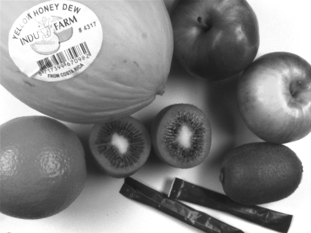
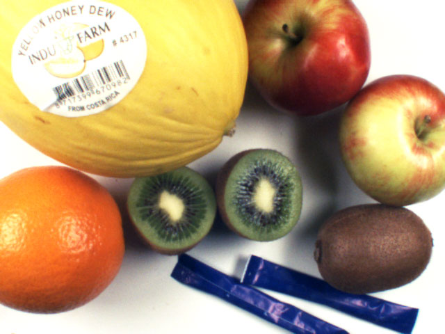
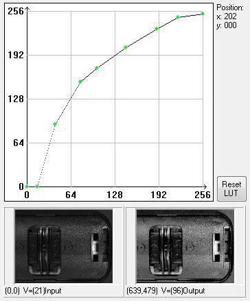
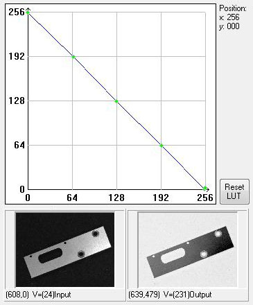
By means of LUTs, the brightness information of each individual pixel can be translated into a new value. For this purpose you can create and write a table that defines which shade of grey (from 0 to 255 in case of an 8-bit monochrome camera) receives which target value.
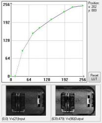
Image with LUT correction
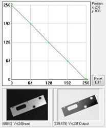
Image with LUT correction
By means of LUTs, the brightness information of each individual pixel can be translated into a new value. For this purpose you can create and write a table that defines which shade of grey (from 0 to 255 in case of an 8-bit monochrome camera) receives which target value.
Shading correction
In many cases, a continuous brightness decrease can be observed in the camera image towards the margin.
Typical causes for this are:
- Vignetting effects of the camera optics
- Too little or design-related inhomogeneous illumination which does not light the entire picture in a uniform way.
- Shading effects due to micro-lenses on CCD sensors which are very large compared to the lens mount of the camera (C-mount / F-mount). Micro-lenses on pixels at the sensor edge also cause vignetting due to incident light at angles. Significant shading is the consequence.
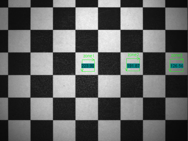
Live image with light falloff
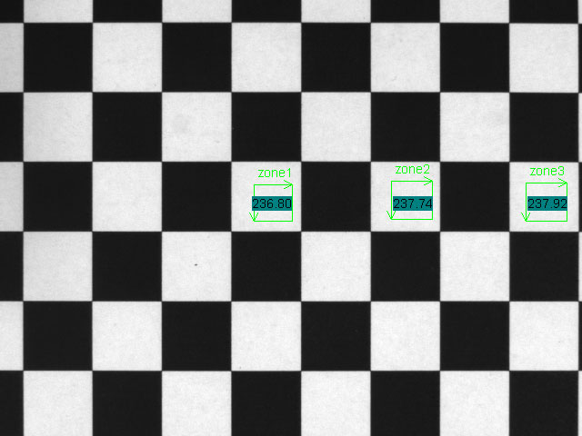
With shading correction
Shading effects due to micro-lenses on CCD sensors which are very large compared to the lens mount of the camera (C-mount / F-mount). Micro-lenses on pixels at the sensor edge also cause vignetting due to incident light at angles. Significant shading is the consequence.
Pixel error correction
Even in case of modern CCDs but especially in case of CMOS sensors, single pixels may be defective or appear brighter or darker than neighbouring pixels using the same exposure. The defective pixels, which are the most disturbing, are pixels which become additionally charged due to insufficient or defective insulation on the semiconductor and destroy the actual image information by too many free charge carriers. These pixel errors appear as very bright dots in the image. If there are several pixel errors of this kind, the image looks like a "starry sky". In case of 1-CCD colour cameras, these bright dots can even appear coloured after the signal processing due to the Bayer mosaic.
Pixels with extremely low or high output characteristics can be eliminated by means of suitable calibration by interpolation with neighbouring pixels. This is often done ex works by the manufacturers. However, these effects often appear after certain aging of the sensor or under special environmental conditions. When using high-quality cameras, the user can execute a balancing at any time in order to compensate these faulty pixels.
Bayer-to-RGB conversion
State-of-the-art industrial colour cameras can transfer their data in different colour formats. The actual colour image generated on a single-chip colour camera, however, is in fact a grey scale image with Bayer mosaic. In a typical pixel arrangement on the sensors, only red, green or blue light is passed through colour filters on the individual pixels. This leads to a rastered grey scale image. The brightness of the shades of grey corresponds to the respective intensity of the colour. By considering the respective neighbouring pixels, the missing R/G/B values can be acquired and calculated for all pixels. Many colour cameras can directly convert colours (Bayer-to-RGB conversion) by means of an FPGA.
Raw Bayer image
Calulated RGB image
The image can often also be transmitted as a raw Bayer 8-bit grey scale image instead of a digital 24-bit RGB colour image. The colour conversion must nevertheless be done on a frame grabber or by means of PC software. The advantage of the subsequent conversion is the higher frame rate which can be transmitted, as only 8-bit monochrome and not 24-bit colour information must be transported. If the conversion is already done in the camera, no frame grabber or CPU load of the PC is required.
