")


Image sharpness
It applies to almost all applications that the image must have optimum sharpness in order to achieve the best inspection results. Due to fixed mechanic defaults, the working distance between optics and part is fixed and the focusing must only be carried out once.
Prerequisites for sharp images
- correct focusing of the optics
- high optic quality (and few optical errors) of the lens to be able to resolve finest structures with a contrast and richness of detail as high as possible
- suitable camera sensor with sufficiently high resolution and dynamic image response
- sufficient object contrast which can be optimised by clever lighting techniques
This chapter will mainly explain the correct focusing of the lens.
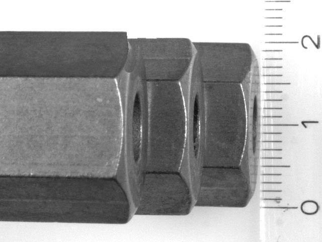
Correct manual focusing and determining the depth of field
In many cases the user will turn the lens back and forth several times by means of the focus ring in order to roughly determine the correct centre position for the image sharpness. Then he/she will probably stop down in order to achieve sufficient depth of field for a uniformly sharp image.
But how do you focus a certain point exactly? For this purpose, the aperture is first opened completely, however, the image would be far too bright in this way. Correct this by reducing the lighting intensity or by reducing the exposure time of the camera. In this setup, the depth of field is at the minimum and only a very small extent in Z-direction appears sharp to the user. Now focus exactly on the inspection area which appears to be especially important (or which is exactly in between the inspection features to be captured). Then it is common to stop down again and re-adapt the intensity of the lighting (or the exposure time).
The depth of field area is now so large that height differences in the part feed can no longer result in blurred images:
Depth of field
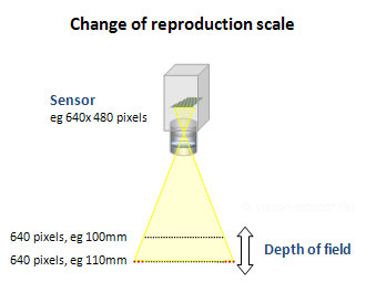
Reproduction scale
However, you must observe that, in case of entocentric lenses, the changed working distance leads to a change in scale and the measuring result can be smaller or larger!
Correct focusing by means of software
By means of simple standards tools, the image processor can determine the image sharpness. A sharp image is characterised by an image contrast at the object edges.
A simple bar pattern with black-and-white stripes helps for this purpose. Use an edge scanning in order to count the edges or a measuring tool from your image processing tool set. Now pull the test distance precisely vertical to the bar edge (from left to right) and observe the gradient of the edges in the gradient graph.
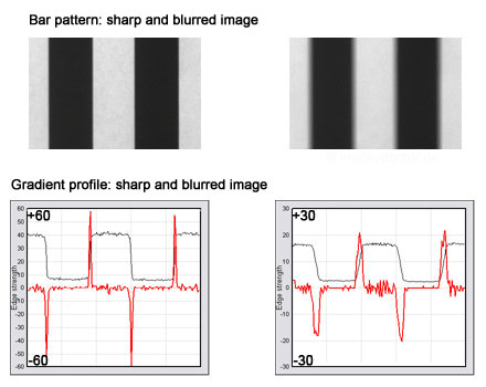 |
The gradient of the brightness profile (read curve in the diagrams) is all the larger, the fewer pixels are needed for the change from bright to dark (or vice versa).Another method is the use of an extensively scanning intensity tool which provides pixel statistics values and a histogram.
|
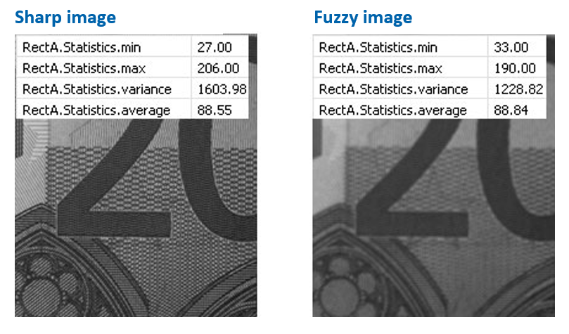
Watch a small image area with a pattern structure. The grey scale histogram for a sharp picture has larger minimum and maximum values and a larger standard variance than that of a blurred image. The average value of the shades of grey, however, does not vary.
Attention: the maximum value of such functions depends on the image content and the general image brightness. Please also observe that there is no overexposure in the inspection tool area which destroys shades of grey.
Please use such software methods to check whether all object planes to be spatially detected are correctly focused and whether the depth of field is sufficient for your measuring application.
Tip:Further information on correct focusing of optics can be found in the download area "Service > Documents" of this website.