")


Image sharpness and depth of field (DOF)
A prerequisite for robust inspection is a sharp image in most of the cases. In Z-direction (towards the camera and away from it) only a small area within certain limits is sharp: The depth of field is the scene space in depth, away from camera and optics, which appears sufficiently sharp in the video image generated by the camera. A sharp image impression is given up to an image unsharpness of approximately one pixel, in measuring applications, however, it should be kept as low as possible. For inspection applications it is important that all features to be inspected are located within this depth of field area.
Calculation of the depth of field
The exact calculation of the expansion of the depth of field is somewhat more complex. Therefore you can find a complete calculation tool for the depth of field in the "Service" area. The formula used with explanations can be found at the end of this page.
Factors for the field of depth
In case of a completely pre-set camera system with fixed mechanic dimensions and already selected components, only the lens aperture has an influence on the field of depth: if the user closes the aperture of the lens, the field of depth in the image is increased. A higher focal ratio, however, results in a longer exposure time. The international aperture scale is arranged in such a way that each step means halving or doubling the exposure time.
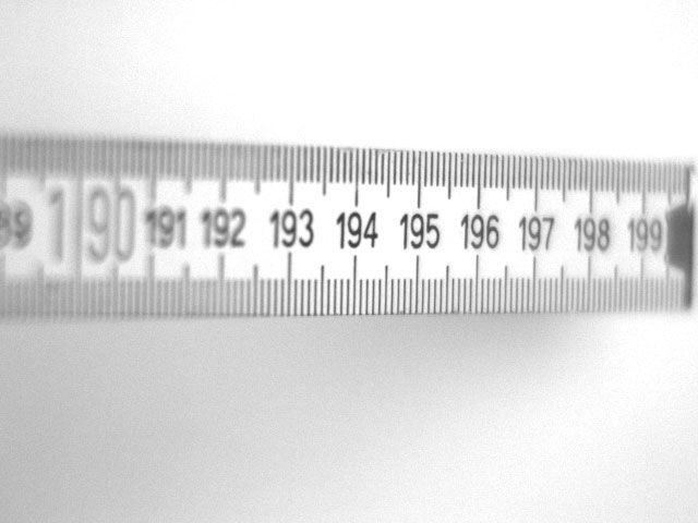
Image: F-stop 1.4, 0.16ms
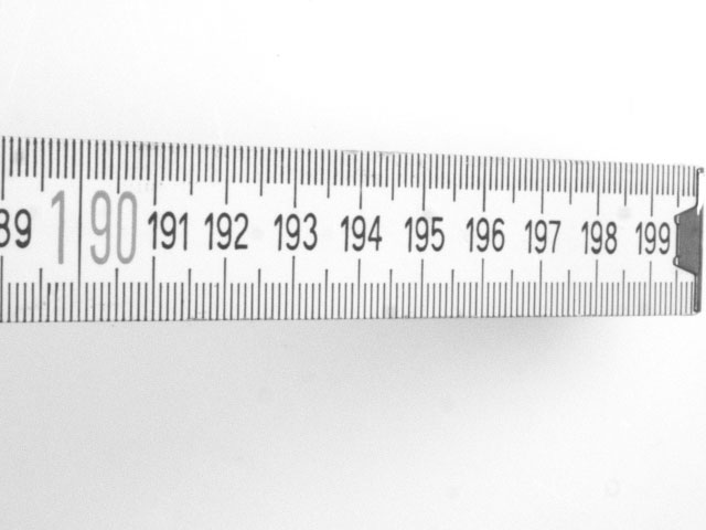
Image: F-stop 16, 20ms
In our example, the optics was focused in such a way that the object y1 is depicted as a sharp image y´1 on the sensor. An object which is closer to the optics generates a point of focus behind the sensor (by re-focusing to this working distance, the lens group would actually move away from the sensor in order to create a sharp image again). Therefore the image on the sensor (image plane) is blurred, the ideal sharp pixel blurs to a larger light spot called blurred spot. The resulting unsharpness is only perceived when the diameter of the blurred spot is larger than the camera pixel and its image information is depicted on neighbouring pixels.
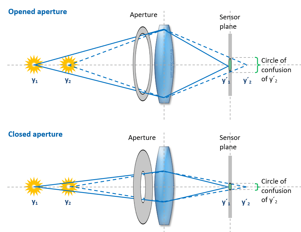 |
By stopping down the optics, the optical path is artificially vignetted and the blurred spot on the image sensor becomes smaller. The objects y1 and y2 can now be much further away from each other in order to create the same blurred spot as in figure a).
By stopping down the optics, the optical path is artificially vignetted and the blurred spot on the image sensor becomes smaller. The objects y1 and y2 can now be much further away from each other in order to create the same blurred spot as in figure a).
The field of depth is the larger...
- the further away the test object (similar, nearly parallel rays of light for both imaging cases)
- the smaller the focal length of the optics, therefore: the smaller the sensor, as it requires smaller focal lengths.
- the smaller the adjusted aperture (see figures)
- the larger the camera pixels: the blurred spot can be larger before it is recognisable as a negative effect on neighbouring pixel structures.
Formulae to calculate the depth of field
The exact calculation of the expansion of the depth of field requires several individual calculations. The formulae used here are based on the publication by Greenleaf, Allen R., Photographic Optics, The MacMillan Company, New York, 1950, p. 25-27.
However, these are only simple approximate equations, just like any other equations published on this topic. Image sharpness and depth of field are strongly influenced by the optic design and the optical errors. An unsharpness of the image points is additionally caused by chromatic and spherical aberration, coma and astigmatism and can make up one entire pixel already in case of very small camera pixels.
Hyperfocal distance:
It refers to the object distance at which objects lying in the infinite can only just be depicted with an acceptable unsharpness if precisely this object distance is focused. Then the field of depth stretches from half the hyperfocal distance to the infinite. First the hyperfocal distance must be calculated:
H= (f´* f´) / (N * c) + f´
Minimum focus distance for acceptable image sharpness:
a near= a (H - f´) / (H + a - 2* f´)
Maximum focus distance for acceptable image sharpness:
a far= a (H - f´) / (H-a)
Total depth of field:
a near - a far
Important variables:
| H |
Hyperfocal distance in mm |
| a near |
Minimum focus distance for acceptable image sharpness in mm |
| a far |
Maximum focus distance for acceptable image sharpness in mm |
| a |
Object distance |
| f´ | Focal length of the lens in mm |
| N | Focal ratio of the optics |
| c |
Blurred spot in mm, typically double pixel size |