Illumination techniques for line scan cameras
A line scan camera application eventually only requires a thin line of light as illumination, as only a 1-pixel wide line is detected by the sensor at once. However, it is important for all line scan camera applications that the light is as bright as possible and has an extremely high frequency in order to avoid flickering.
These lights are used:
- Line-shaped LED lighting (with focusing lens for incident light / with diffusor for transmitted light): For hardly time-critical applications and short illumination distances, LED-based line lights have become prevalent. Their intensity is usually lower than that of halogen cold-light sources, however, they have a very long service life and are available in different light colours. Due to the simple design and high homogeneity they are common in transmitted light applications, as the camera looks directly into the lighting, the brightness is always sufficient. Extremely bright LED incident light illumination (flash light operation unfortunately not possible for line scan camera applications) requires massive cooling elements or is even water-cooled and thus increasingly replaces halogen cold-light sources in incident light operation. The illumination of long distances is expensive.
- Halogen or LED cold-light sources with line-shaped optical fibres: They are classic lightings for line scan camera applications. A halogen light source (comparable to a slide projector) generates very bright light with approximately 200 watts which is focused via an optical fibre and a line cross-section converter with cylindrical ancillary lens as a thin line. Both incident light and dark field technique can be realised easily. The disadvantage of this technology is the generation of only white halogen light and the short service life of the illuminant. The illumination of long distances is expensive.
- Fluorescent tubes with high-frequency ballast: "neon lamps" in rod shape are a cheap form of illumination of line scan camera applications. However, they can only be used as diffuse incident light or transmitted light. They are often applied as cheap illumination of long distances. Yet the service life of the tubes is strongly restricted, the light colour is limited to white only. Look for extremely fast-switching ballasts.
Incident light illumination for line scan cameras
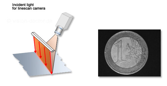
- This is the standard method for the surface inspection using line scan cameras.
- Camera and lighting are arranged in such a way that the camera is at the reflection angle of the lighting (angle of incidence = angle of reflection). In this way as much incident light is detected as possible.
- This works especially well in case of reflecting materials. Bright areas appear bright, dark areas dark in this way.
- If the angles of surface structures are not suitable aligned but tilted, they also appear dark in the camera image. Scratches in the surface or inclined phases, etc. have darker shades of grey in the image.
|
Dark field illumination for line scan cameras
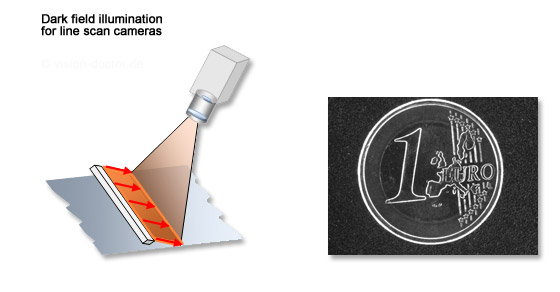
- Line scan cameras, too, can be used to achieve a dark field effect. For this purpose, the illumination is not aligned onto the component at the angle of reflection, but clearly flatter.
- The directly reflected light does not hit the camera, the image field appears dark.
- Only the faint stray light is detected by the camera, therefore a lot of light is required for this technique.
- Scratches, slots, elevations or embossments appear bright as they stray the light due to their uneven surface. Ideal method to detect surface defects on smooth materials.
|
Backlight illumination for line scan cameras
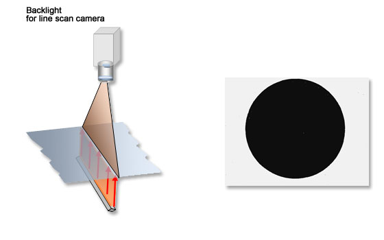
- In this illumination scenario, camera and illumination are exactly opposite of each other, the test object is right in between.
- The contours of non-translucent materials become visible in this way, edge chippings can be detected and the component can be measured.
- In case of transparent objects (like glasses and foils, etc.) this method can be used to make bubbles or cracks in the material or edge chippings visible.
|
Tips for the alignment of line illumination
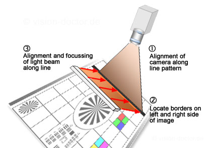
The line scan cameras often detect only a few 1/10 mm wide stripes of the image field. This is to be hit and illuminated exactly by means of the equally thin line of light:
 |
- Use a calibration target with a slightly wider black stripe (possibly also with crosswise division) and align it at right angles to the conveyor.
- Change the trigger type of the camera to freely running mode without the use of encoder or trigger signals.
- Position the calibration target in such a way that the complete length of the black stripe is detected by the line scan camera. As the image block typically consists of many image lines, it must now be completely black.
- Take a pen and draw a line over the stripe. Now you can determine the right and left positions in the camera image. If necessary, mark them also on the calibration target.
- Now you know the exact position which is detected by the camera. Align the angle and working distance of your illumination as required and, if possible, focus the light beam for maximum brightness.


